Study of Logic Gates
In this post on Study of Logic Gates, you will be getting to know complete details on Logic Gates (Electric Gates), Logic Gate Symbols, Logic Diagram and truth tables.
All necessary information on Logics Gates Basics has been provided.
What is meant by Logic Gate?
A circuit that works based on the logical decision and the process is called as Logic Gates. Each gate has one or more inputs and only one output.
The “0” refers to Low or false and the “1” refers to High or true.
Code Conversion | Excess-3 -> BCD Converter
Different types and Study Of Logic Gates:
#1. AND Gate:
The AND Gate performs the logical multiplication operation which is commonly known as AND function.
- # If both the inputs are high then the output is high.
- # If any one of the input is Low then the Output is Low.
The IC used for used for AND gate is IC 7408.
Pin Diagram of AND Gate:
The Input pins are (1,2), (4,5), (9,10), (12,13) and the Output Pins are (3,6,8,11).
Vcc: 14
GND: 7
Symbol of AND Gate:

Truth Table of AND Gate:

Code converter | BCD -> Excess-3 Converter
#2. OR Gate:
The Gate which performs logical addition operation is known as OR Gate which is also known as OR function.
- #If any one of the input is high then the output is high.
- #If both the inputs are low then the output is low.
The IC used for OR Gate is 7432.
Pin diagram of OR Gate:

The Input pins are (1,2), (4,5), (9,10), (12,13) and the Output Pins are (3,6,8,11).
Vcc: 14
GND: 7
Symbol of OR Gate:

Truth Table of OR Gate:

Code Conversion | Gray Code -> Binary Converter
#3. NOT Gate:
The Gate which performs inversion operation is called as NOT Gate.
- #If the Input is high, then the output is low.
- #If the Input is low, then the output is high.
The IC used for NOT gate is IC 7404.
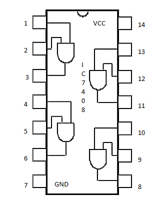
Pin diagram of NOT Gate:

The Input pins are (1,3,5,9,11,13) and the Output Pins are (2,4,6,8,10,12).
Vcc: 14
GND: 7
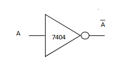
Symbol Of NOT Gate:
Truth Table of NOT Gate:

Code Conversion | Binary -> Gray code Converter
#4. X-OR Gate:
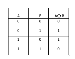
- #If both the inputs are same, the output is Low.
- #If both the inputs are not the same, the output is High.
Pin Diagram of X-OR Gate:

The Input pins are (1,2), (4,5), (9,10), (12,13) and the Output Pins are (3,6,8,11).
Vcc: 14
GND: 7
Symbol of X-OR Gate:

Truth Table of XOR Gate:
#5. NOR Gate:
NOR is the inversion of OR Gate.
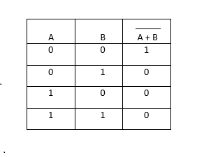
- #If both the inputs are low, the output is high.
- #All other cases, the output is low.
Pin Diagram of NOR Gate:

The Input pins are (2,3), (5,6), (8,9), (11,12) and the Output Pins are (1,4,10,13).
Vcc: 14
GND: 7
Symbol of NOR gate:

Truth Table of NOR Gate:
Kirchoff’s Law | Voltage Law and Current Law
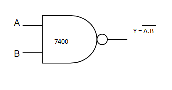
#6. NAND Gate:
NAND Gate is a combination NOT Gate and AND Gate. In other words, NAND Gate is an inversion of AND gate.
Pin Diagram of NOR Gate:

The Input pins are (1,2), (4,5), (9,10), (12,13) and the Output Pins are (3,6,8,11).
Vcc: 14
GND: 7
Symbol of NAND Gate:
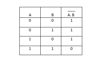
Truth Table of NAND Gate:
That’s all in Logic Gates Basics.